Bracing for the future
by ciara_lalor-lindo | October 13, 2026 9:00 am
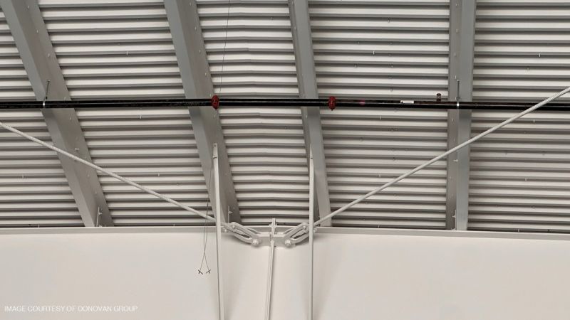
In metal building design, owners want to know the cost and delivery. Architects think about openings, elevations, space planning, and how the building will function. Engineers work through load paths and code requirements. Erectors focus on how the building will actually come together in the field.
Bracing sits in the middle of all of that. It can affect bay spacing, framed openings, interior flexibility, equipment layouts, field labor, inspection, and the way the finished structure supports the architect’s intent. It can also significantly affect how a metal building withstands natural disasters.
On February 22, 2011, Christchurch in New Zealand experienced a 6.3 magnitude earthquake, causing severe damage across Christchurch and Lyttelton, killing 185 people[1] and injuring thousands more. For engineers, manufacturers, and builders working in New Zealand, it was a serious reminder that structural performance depends on the details.¹
Connections matter. Load paths matter. Ductility matters. Bracing systems matter.
Research published in the Bulletin of the New Zealand Society for Earthquake Engineering found that steel structures generally performed well during the Christchurch earthquake sequence. The notable exceptions were localized fractures in some eccentrically braced frame links, brace connection failures in which connections could not develop the brace’s full strength, and widespread collapse of industrial storage racks associated with connection failures and local column buckling[2].²
That distinction is worth remembering. The lesson here is not that steel buildings failed as a category, but that real-world performance depends on how the full structural system is detailed, connected, and installed, and how it responds under extreme demand. Bringing these insights to North American metal building design allows for adaptable consideration of seismic and weather events across the continent.
Christchurch did not produce a single North American metal building standard that can be traced directly to the event. Its influence was broader. The Canterbury Earthquakes Royal Commission recommended changes to New Zealand design practice and standards, including a specific recommendation that NZS 3404 be amended to require redundancy in structures that use eccentrically braced frames for seismic resistance. The Commission also emphasized that designers must clearly define load paths and ensure that details have sufficient strength and ductility to perform as intended[3].³
For the metal building industry, the lesson is less about one new prescriptive rule and more about a design mindset: bracing, connections, ductility, redundancy, and constructability must be considered together as part of the complete lateral-force-resisting system.
In practice, the load is prescribed. The solution is designed.
Bracing requirements are driven by the applicable building code, site-specific loading conditions, building geometry, and use. Depending on location, a structure may need to resist wind, seismic, snow, or a combination of loads. Those forces establish the required structural demand, but different bracing systems can meet that demand in different ways.
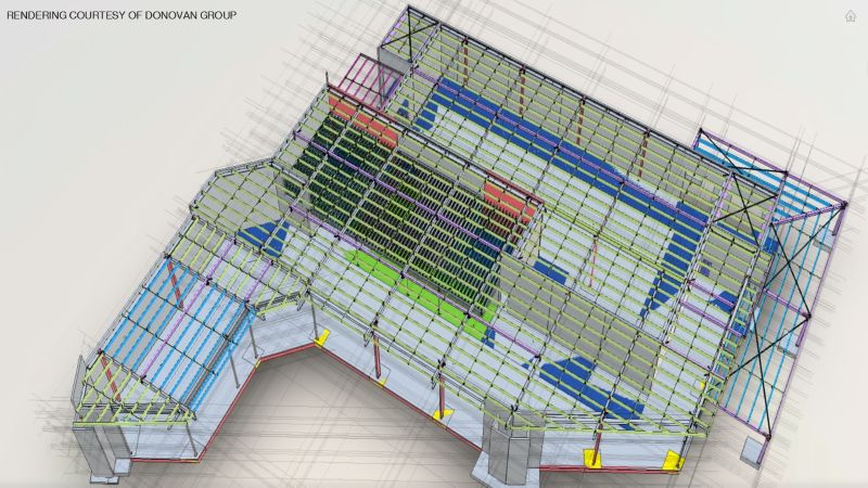
A storage facility for Beck’s in New Madrid, Mo., illustrates how site conditions can drive the lateral system. Seismic demand was a key design consideration, requiring a robust bracing solution. In the cited application, higher-capacity tension bracing was used in place of standard 3 x 3 in. (76.2 x 76.2 mm) angle bracing. The structural requirements did not change, but the way the building resisted the load did. Lighter components reduced the amount of material the erection crew had to move and position, while the bracing could be installed as framing progressed. That became particularly valuable after weather delays placed pressure on the construction schedule.
Building function can shape bracing in a different way. At a 150,000 sf (13,935.5 m2) manufacturing facility in West Jordan, Utah, a building was designed to support the production of mobile data centers. Crane bays created steep brace geometries and introduced additional connection and installation considerations. A conventional rod bracing approach would have required custom slope washers at some locations, while double-rod bays would have created the potential for turnbuckle conflicts.
The project team coordinated a higher-capacity tension bracing system that reduced double 1.25 in. (31.75 mm) rod X-bracing to a single 1 in. (25.4 mm) X-bracing system in the cited application. The required capacity was still governed by engineering, but the selected system worked within the physical constraints created by the facility’s function. The benefit was not simply aesthetic. In a manufacturing environment, every structural element must be coordinated with equipment, material flow, crane access, maintenance zones, and worker circulation. By reducing the amount of rod bracing required in the cited locations, the lateral system became less congested and easier to coordinate with the building’s operational needs.
As demonstrated in this design, a more streamlined bracing layout can reduce conflicts around crane bays and equipment zones, simplify connection detailing, and limit the number of components competing for space within the same braced bay. It can also make the finished structure cleaner and easier to navigate visually, which matters in facilities where large equipment, overhead movement, and clear work zones are part of day-to-day operations. The influence of bracing selection can also be seen in the number of locations required to resist lateral forces.
On a 57,500 sf (5,341.9 m2) retail building in Jerome, Idaho, a higher-capacity tension bracing system reduced the roof bracing layout from five braced bays to two. Lateral forces are the sideways forces a building must resist, most commonly from wind or seismic movement. The building’s location, size, exposure, occupancy, and site conditions help determine those forces. Once established by code and engineering analysis, the bracing system becomes one of the ways those forces are collected and transferred through the structure.
In Jerome, the roof bracing was part of that lateral-force resisting system. By using a higher-capacity tension bracing system, the design team was able to resist the required demand with fewer braced bays. Traditional rod-bracing systems often rely on multiple rods, turnbuckles, and connection components. Turnbuckles allow rods to be tensioned, but they can also add congestion where rods cross or where multiple components meet.
Fewer braced bays meant fewer roof locations with diagonal bracing, fewer connection points to coordinate, and less work for the erection team at elevation.
Again, the required structural performance did not change. What changed was how the resistance was distributed through the structure. For the erection team, fewer braced bays meant less work at elevation. From a broader design perspective, reducing the number of brace locations can also create more options when coordinating openings, circulation, and other building requirements, although the final brace layout remains an engineering decision.
Brace capacity, connection details, and the number and location of braced bays can affect framed openings, equipment layouts, circulation, and field labor. The design process, therefore, becomes a coordination exercise.
Owners establish how the facility must function. Architects define space, access, and openings. Engineers establish the load path and required capacity. Metal building manufacturers and construction teams then help turn that design into a system that can be fabricated and erected efficiently.
Notes
1 Learn more about the Christchurch earthquake with NZ History, “Christchurch earthquake kills 185.”
2 Read the “Steel structures damage from the Christchurch earthquake series of 2010 and 2011” by Clifton, Bruneau, MacRae, Leon, and Fussell from the Bulletin of the New Zealand Society for Earthquake Engineering.
3 Read the “Royal Commission of Inquiry into Building Failure Caused by the Canterbury Earthquakes”.
Michael Ryan is the director of sales and operations in North America for the Donovan Group.[4] He is an allied member of the American Institute of Architects[5], an active member of the Metal Building Manufacturers Association,[6] and the Metal Building Contractors and Erectors Association[7].
This feature originally appeared in the August/September 2026 edition of Metal Architecture, which you can find in our Digital Edition Archives.
- Christchurch and Lyttelton, killing 185 people: https://nzhistory.govt.nz/page/christchurch-earthquake-kills-185
- connection failures and local column buckling: https://www.researchgate.net/publication/288714686_Steel_structures_damage_from_the_Christchurch_earthquake_series_of_2010_and_2011
- details have sufficient strength and ductility to perform as intended: https://canterbury.royalcommission.govt.nz/
- Donovan Group.: https://donovangroup.com/
- American Institute of Architects: https://www.aia.org/
- Metal Building Manufacturers Association,: https://mbma.com/
- Metal Building Contractors and Erectors Association: https://www.mbcea.org/
Source URL: https://www.metalarchitecture.com/articles/features/bracing-for-the-future/