Photo courtesy MBMA
Metal building systems are the most prevalent construction solution for one-and two-story commercial structures. In fact, although numbers vary by source, the Metal Building Manufacturers Association (MBMA) reports that approximately 30 percent of all commercial buildings in the United States today are created with metal building technology. Although metal buildings are inherently fire-resistant, there are various fire safety considerations to take into account when specifying a metal building.
In 2009, MBMA commissioned the first edition of the Fire Resistance Design Guide for Metal Building Systems (Design Guide), which was published in 2010. This document became a standard resource for specifiers and code officials, as well as design professionals in the architecture and engineering disciplines. The guide consolidated and documented the available information on common fire-resistant construction practices for metal building systems and the 12 then-existing MBMA-sponsored fire-resistance-rated assemblies, as well as additional non-MBMA assemblies that could be used in metal buildings, either to meet design needs or to expand the range of choices for fire-resistant designs.
MBMA released a new edition in October 2024. The primary author of the more than 100-page manual is Nestor Iwankiw, P.E., SE, Ph.D., under the direction and advisory review of MBMA’s Fire and Insurance Committee. Dr. Iwankiw is a consultant with Jensen Hughes, a firm specializing in consulting for fire protection engineering, forensic engineering, and security.
This revised edition of the Design Guide is updated to reference the 2018 International Building Code (IBC) and to cover related fire resistance developments since 2010, including:
- Several newer assemblies developed by MBMA
- Fire resistance of metal roofs that support photovoltaic panels
- Current code requirements for fire protection of voids between fire barrier walls and unrated roofs
The following descriptions provide an overview of some key specification-related elements in the Design Guide.
Foundational specification and design considerations
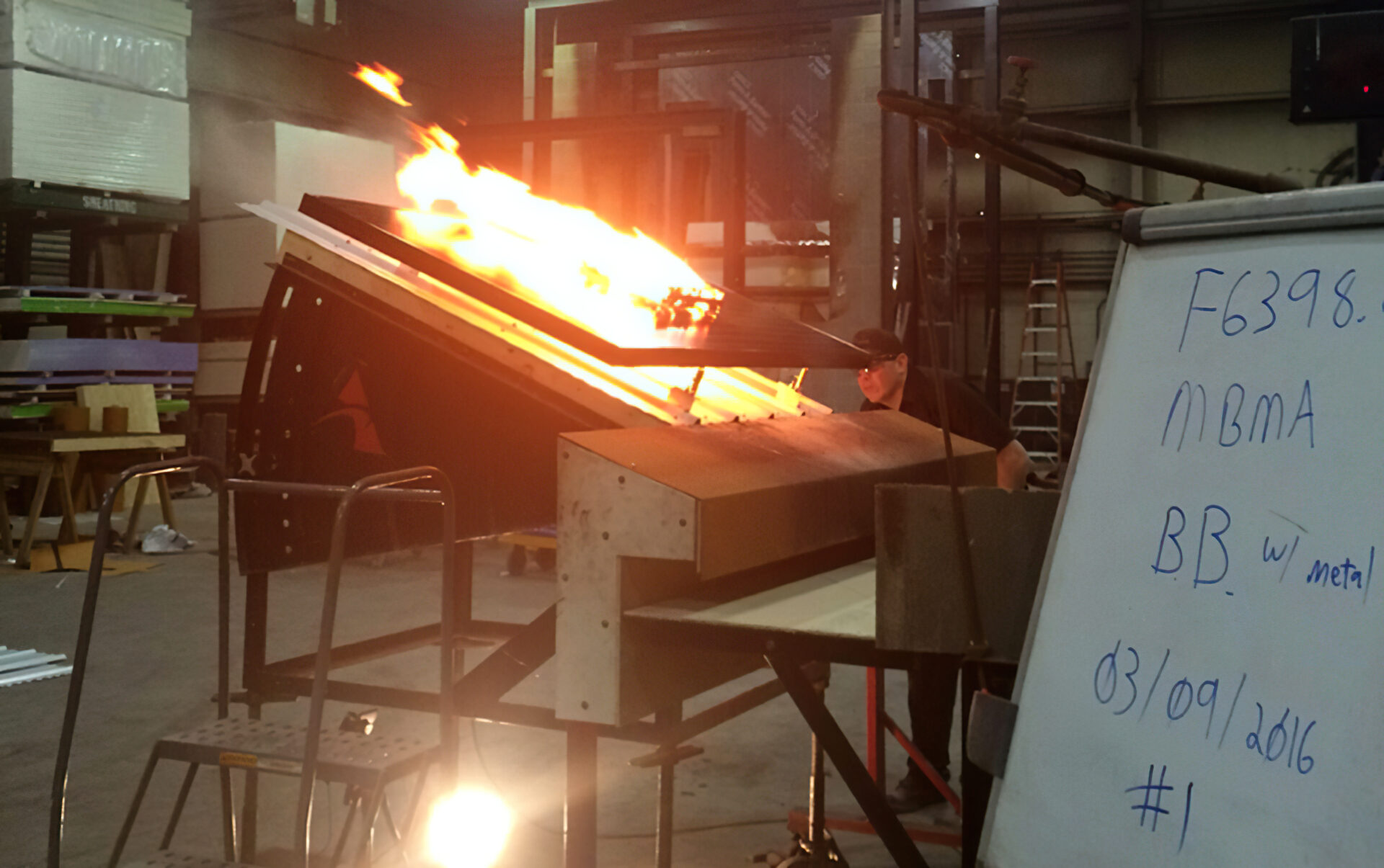
Burning a brand on the surface of a photovoltaic (PV) module.
Photo courtesy MBMA
Metal building systems are noncombustible structures that consist of primary framing (composed of built-up constant depth or web-tapered structural steel frames), secondary members that are cold-formed steel or steel joists, a metal panel roof system, and exterior wall cladding. These components and assemblies are manufactured to permit plant and/or field inspection before assembly or erection.
Today’s metal building systems also look different from those constructed in past decades. Metal buildings incorporate many architectural finishes to provide the aesthetics envisioned by the designers for specific applications such as churches, schools, shopping centers, and office buildings.
Building codes do not require the elements of single-story metal buildings to have structural fire protection for most applications due to their noncombustible steel construction, occupancy types, and limited heights and areas. However, situations arise where portions of a metal building, or certain types of elements, are required to be protected for fire resistance. These circumstances may be due to building design factors such as interior area or occupancy, wall separations, multiple story levels, exit distances, and/or a building’s proximity to an adjacent property line.
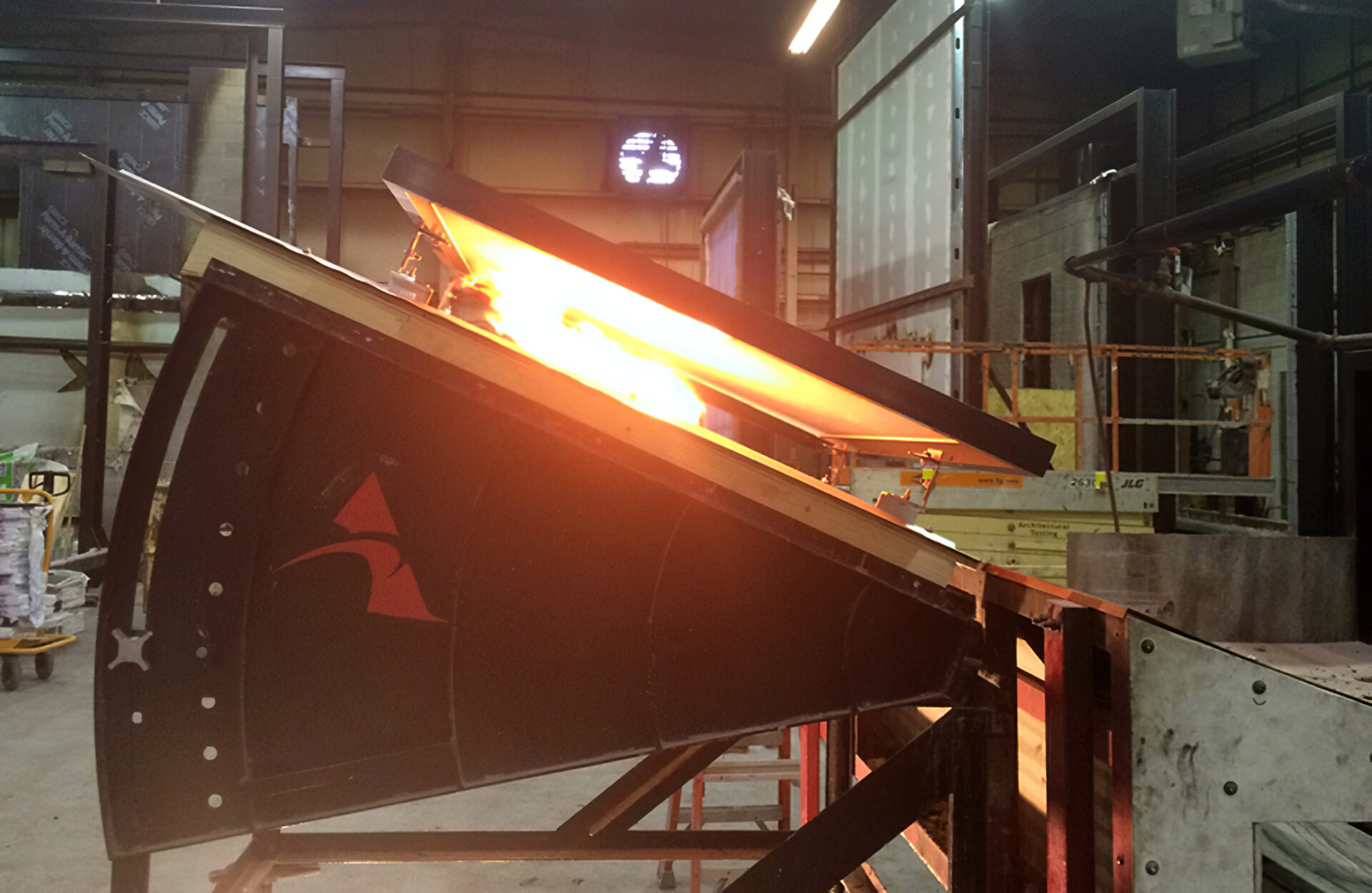
Burning a brand between a photovoltaic (PV) module and roof assembly.
Photo courtesy MBMA
The main building elements that may require a fire-resistance rating (FRR) are the columns, the walls, and the roof. Walls may be either rated for vertical load-bearing or non-load-bearing applications, as well as for fire exposures from one or both sides of the wall. Standard FRRs for such assemblies have been developed over the decades in the United States for the different construction elements and fire-protection materials.
Most proprietary listings of specific construction products and manufacturers are maintained through the UL Solutions online database, “UL Product iQ,” although other accredited test laboratories in the United States also certify listed assemblies’ FRRs. The UL Solutions assembly listings are updated continuously. Other generic, non-product-specific construction assemblies that have been rated for fire resistance may be cited in the building code itself, as well as in various industry and trade publications.
Fire-resistance-rated assemblies in metal building design
The types of assemblies directly applicable to metal building construction are load-bearing steel columns, usually tested in accordance with ASTM E 119/UL 263, without any superimposed load and subject only to limiting steel temperatures, load-bearing or non-load-bearing walls, and load-bearing roof assemblies. While the published UL Solutions and other assembly listings may be rated for fire-resistance times of up to four hours, most fire protection requirements for Type IIB metal building designs do not extend beyond one or two hours for some parts of the construction. Accordingly, the MBMA developed assemblies to also parallel these most common one- and two-hour FRR needs. In some cases, however, the exterior walls, area separation walls, or occupancy separation walls may need longer rating times. For these special conditions, other gypsum board and masonry wall assemblies for three- and four-hour ratings have been cross-referenced in the Design Guide.
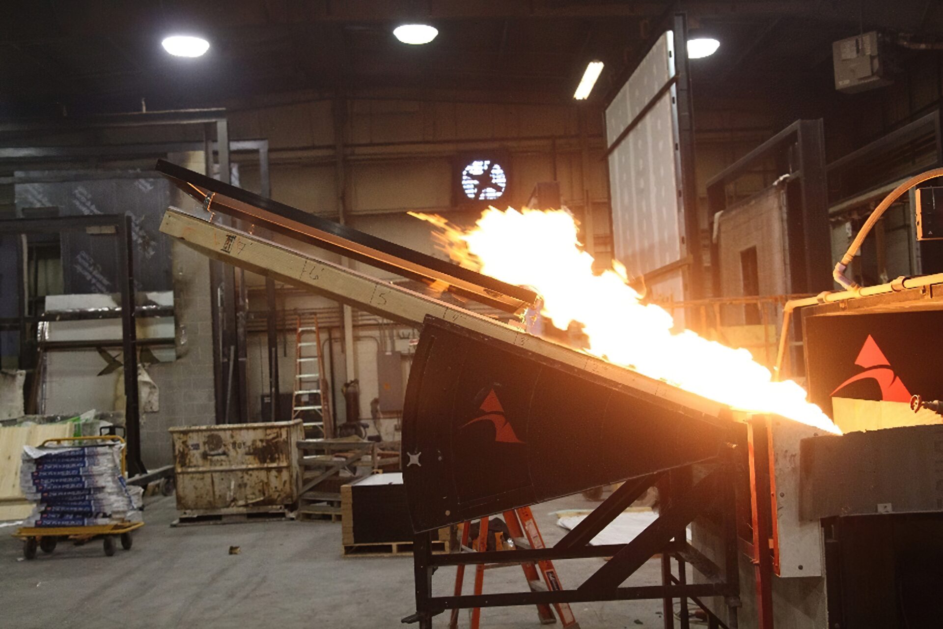
This figure displays a spread of flame test.
Photo courtesy MBMA
The Design Guide includes detailed information on fire-resistance-rated column, roof, and wall assemblies and joint systems, including the newer wall assemblies and joint systems for wall-roof joints and intersections. For example, the section on wall assemblies discusses one- and two-hour FRRs of metal buildings’ interior and exterior walls constructed of cold-formed steel framing (steel studs) and gypsum board. These wall assemblies include UL U425, UL U489, UL V421, and the more recently developed UL W404, UL W413, and UL W447 with its ULC U421 counterpart. Of these, only UL U425 and UL U489 are permitted for load-bearing applications. Interior fire barriers, such as UL U425 and UL W447, may be required in metal buildings for purposes of area, occupancy, or exiting separations. Exterior walls, load-bearing and non-load-bearing, are required by the IBC to comply with the overall fire-resistance criteria for the particular building construction type, as well as those based on fire separation distance to an adjoining lot line. A fire separation distance of at least 9.1 m (30 ft) will avoid the necessity to provide a fire-protected exterior wall for any occupancy and for all construction types.
UL W404 and UL W413 assemblies are noteworthy in several aspects. They permit an increased maximum spacing of the horizontal steel girt supports to 2,290 mm (90 in.) from the 1,220 mm (48 in.) limit in UL V421. The required gypsum board protection is to be installed only on the interior side for either interior or exterior fire exposure, which simplifies the wall construction relative to the required board installation of UL V421 on both faces.
For purposes of energy conservation and code compliance, these two newer exterior wall assemblies also allow the very desirable option for an inclusion of up to 102 mm (4 in.) thickness of rigid foam board insulation within the wall cavity. Also, both UL W404 and UL W413 assemblies allow for the optional use of standard steel stud and wall track framing instead of the furring channel for the installation of the interior gypsum board.
Another important update involves six new HW-D/CJ-D head-of-wall (HOW) fire-resistant joint systems that allow for significantly greater levels of roof insulation to meet updated energy code requirements while maintaining fire safety. The new designs for wall-roof joints between fire-rated assemblies are UL HW-D-0926, UL HW-D-0927, and UL HW-D-0928. For intersections between a fire-rated wall and a non-fire-rated roof, the new designs are UL CJ-D-0029, UL CJ-D-0030, and UL CJ-D-0031. The details of the new joint systems are based on and similar to the other HOW joint systems (UL HW-D-0488, UL HW-D-0489, UL HW-D-0490, UL CJ-D-0005, UL CJ-D-0006, and UL CJ-D-0007). Both sets of designs specify a single layer of glass fiber blanket insulation, compressed between the metal roof panels and the top of an interior wall. The new designs allow for additional insulation, glass fiber or mineral wool, between the purlins, as well as a vapor barrier, as found in filled cavity insulation systems and liner insulation systems.
Fire resistance of metal roofs with photovoltaic (PV) panels
A new section in the Design Guide describes the use of PV panels on metal building roofs and the resultant fire safety considerations. A standing seam metal roof is an ideal platform for PV since the metal roof’s service life is compatible with the PV array’s service life, and the system can be attached without roof penetrations.
The IBC contains fire safety requirements for PV assemblies installed on roof systems. There have been significant changes in the last few editions (2012, 2015, 2018, and 2021), resulting in similar provisions in different locations. Prior to the 2012 IBC, there were no fire testing requirements for such systems; there were only requirements to test modules or panels. The IBC references several UL Standards, 1703, 61730-1, 61730-2, and 2703. Mounting hardware should be listed to UL 2703, Standard for Mounting Systems, Mounting Devices, Clamping/ Retention Devices, and Ground Lugs for Use with Flat-Plate Photovoltaic Modules and Panels, and PV modules should be listed to UL 1703, Standard for Flat-Plate Photovoltaic Modules and Panels, or both UL 61730-1, Photovoltaic (PV) Module Safety Qualification – Part 1: Requirements for Construction and UL61730-2, Photovoltaic (PV) Module Safety Qualification – Part 2: Requirements for Testing.
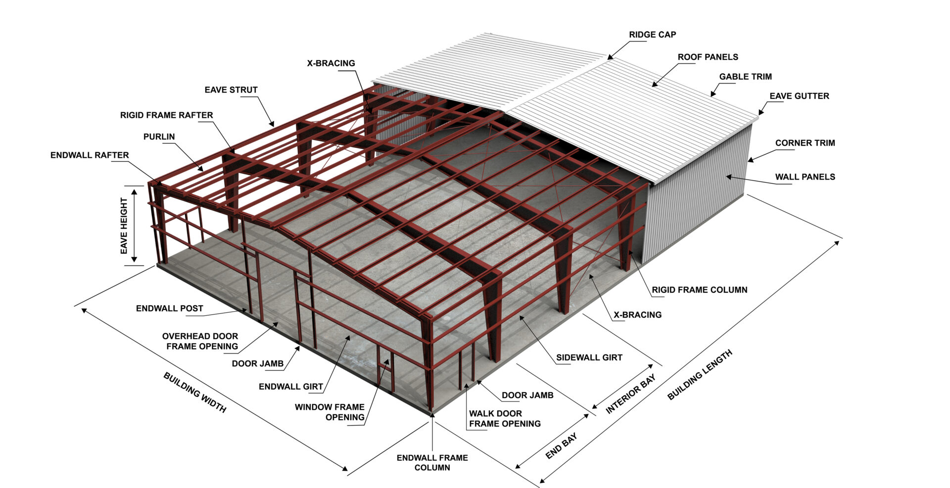
Photo courtesy MBMA
Section 11.1 of UL 2703 covers the fire-resistance requirements for PV systems, which refers to Section 15 for fire testing. The idea behind the fire testing is to show how a fire progresses into and through a PV system. PV module, the mounting system, and the roof system are tested through a series of two types of tests, burning brand and spread of flame, as shown in Figure 1 (page 40), Figure 2 (page 42), and Figure 3 (page 44). This testing has been standardized around a roof with a marginal Class A fire classification, as defined by the IBC. The marginal Class A roofs are of combustible construction as follows:
- Asphalt shingles for roof slopes of 2:12 or greater
- PVC or TPO for slopes of less than 2:12
The IBC, by referencing UL Standards, is silent with respect to PV systems located on noncombustible roof systems. Therefore, the testing of PV systems installed over noncombustible roof systems, such as the typical standing seam metal roofs used in metal building systems, is dependent on the edition of the IBC and its referenced UL Standards. If the IBC edition of record is 2018 or earlier, the PV system is required to be tested over the combustible (marginal Class A) roof covering to obtain a System Fire Class Rating. Alternatively, a code variance petition may be filed in this regard.
These fire safety requirements for PV installation on roofs were considered an undue burden for the qualification of such construction on noncombustible standing seam metal roofs and similar metal roofs. Thanks to industry-wide efforts, in cooperation with MBMA, this burden was mitigated through a fire test exception in the 2019 UL 2703 standard that is referenced in the 2021 IBC. The exception states:
“The fire tests outlined in this section are not required for systems that meet all the following requirements:
- Modules or panels of Type 1, Type 2, or Type 3 as defined by UL 1703 or UL 61730-2;
- Rack mounting systems, that comply with this standard, constructed of minimum 98 [percent] (by weight) noncombustible materials, as defined by ASTM E136; and
- Installed over Class A roof assemblies with the following noncombustible roof coverings:
- Clay tile
- Concrete tile
- Metal panels made from steel, minimum 28 Ga ferrous panels or shingles
These systems shall be identified as having a Class A fire rating.”
Limitations and adaptations of rated assemblies
Photo courtesy MBMA
Standard fire-resistance tests and their derived assembly ratings have been the conventional and traditional way of demonstrating compliance with the building code requirements for fire protection. However, the use of assembly design listings presupposes that the construction matches an assembly that has been previously tested or approved. If the assembly is modified or a different material is substituted in the actual construction, the as-built assembly may not be acceptable to the authority having jurisdiction (AHJ). Another standard fire test may be required to develop the appropriate FRRs for this prototype.
Additional testing is often considered to not be feasible in terms of cost and schedule, especially for in-progress construction projects. For these reasons, the second edition of the Design Guide includes a new section on several approaches that have been used to expand the practical application range of a given rated assembly. The approaches include the following:
- Minimum and maximum values
- Restrained and unrestrained ratings
- Differentiation between normal-weight and lightweight concrete
- Allowable material or product substitutions
- Steel beam minimum grade assumed by UL Solutions
- Interior building applications per UL Solutions
- Attachments to structural steel per UL Solutions
- Other BXUV guide information
- Structural steel transitions between unrated and rated construction
- Infill of the void between the rated fire-barrier wall and the unrated roof or wall
Even with the various allowable application extensions of fire-resistance-rated assemblies, their potential coverage is still quite limited relative to the full universe of possibilities and needs of design and construction. Another way to resolve unexpected issues, AHJ questions, or differences between the as-designed/installed construction and the referenced rated assembly is to conduct an independent engineering study to provide an engineering judgment letter/report. While the outcome of the engineering judgment may deviate from the solution initially desired or preferred by the project team, this approach does offer a practical and technically justifiable process. The work may involve a review and assessment of published fire performance and the available test data, some level of engineering computations or analysis, and/or comparisons to other similar rated assemblies. In some cases, such as for requested substitutions or additions of specific fire protection or insulation products, there may be insufficient empirical data available to render a suitable engineering judgment for the proposed alternative assembly without additional fire testing.
Steel member dimensions for fire resistance
Listings of fire-resistance-rated designs with gypsum board, spray-applied fire-resistive material, and intumescent fire-resistive material protection usually identify the relatively small steel shapes of the tested assembly because of the size and facility limitations of the test laboratories. The key parameter used in the member substitution equations is the steel shape’s W/D, where W is the weight of the steel shape and D is the heated perimeter of the inside surface of the insulation. However, these designs and substitution equations were derived for standard fire exposures on prismatic (constant cross-section) steel shapes.
Non-prismatic built-up steel columns are commonly used in metal building system construction. Using the most critical (lowest) W/D value along the entire non-prismatic member length being designed for fire resistance is rationally expected to provide a conservative result for the design. The Design Guide provides information on how to determine the most critical W/D value.
Vincent E. Sagan, P.E., F.ASCE, director of codes and standards for the Metal Buildings Manufacturers Association (MBMA), served as the project director for the second edition of the Fire Resistance Design Guide for Metal Building Systems. In addition, he manages research and engineering projects and interacts with U.S. code and standards organizations. He represents MBMA on several ASCE 7 subcommittees. He has more than 30 years of experience in all phases of investigation, design, and construction of buildings and other structures.